Principle
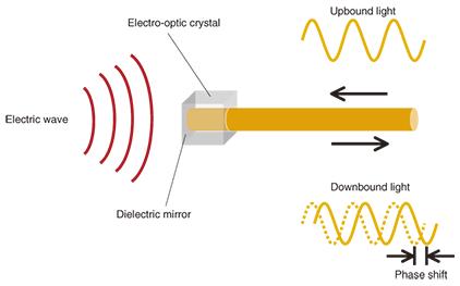
A fiber-optic sensor field strength tester made based on the Pockel effect of special electro-optic crystals (the effect of linear changes in refractive index with external electric field). As shown in Figure 1, when the crystal probe is placed in the power frequency electric field E (or power frequency U is applied to the probe), the optical signal output from the optical cable is modulated by the external electric field E or the external voltage U, and the corresponding light is output. Signal. Thus, the applied electric field E or the applied voltage U can be measured. Figure 1 Schematic diagram of the probe principle
Assemble the electro-optic crystal and its matching optical system in a special probe box to form the measuring sensor of the instrument.
The sensor's own capacitance is about 10pF, and the insulation resistance is >10Ω. It is a passive device with extremely high input impedance.
Structure
The instrument consists of a high input impedance voltage divider, sensor, optical cable and signal processor, as shown in Figure 2.
Figure 2 Instrument principle structure diagram
Features
1. Electric field measurement: The sensor is a field-effect device and only contains special Crystal and glass optical devices, without electronic devices, are passive probes that do not consume energy (no battery is needed inside); the volume is only the size of a matchbox and does not contain metal parts. It is used to measure the electric field strength along the surface of the composite insulator and the electric field of the human body during live operation. The distribution of the original spatial electric field will not be distorted under the conditions of the electric field intensity and the electric field intensity in the substation space.
2. Distributed voltage measurement: The sensor's own capacitance is only about 10pF, and the insulation resistance is >10Ω. When it is used as the secondary voltage measurement element of the high-voltage divider, the resistance is divided The resistance of the high-voltage arm of the voltage device or the capacitive reactance of the high-voltage arm of the capacitive voltage divider can be as high as 1000MΩ to measure the distributed voltage on high-impedance components such as insulator strings and switch series fractures.
3. The optical cable ensures the insulation between the probe and the ground instrument: It can be used for power frequency field strength and power frequency on all transmission lines and high voltage laboratories of 1000kV and below in my country , On-site and laboratory measurement of operating impulse voltage.
Technical parameters
Name | Model | Item | Metrics | Remarks |
Light Fiber Transmission Sense 分 Cloth Electricity Pressure / Field Strong Test Instrument | GDC200 | Voltage Measuring range | 0.5V-600V 200V-40kV | Sensor Voltage divider |
Field strength measurement range | 2V/cm-10kV/cm | |||
| Sensor input resistance | >10000MΩ | |||
Sensor inlet capacitance | <10PF | |||
Voltage divider input impedance | 400MΩ | |||
Frequency response | 7Hz-100kHz | |||
Measurement accuracy | ±1.5% | |||
Sensor size | 2.2×2.8×6cm | |||
Sensor weight | 150g | |||
Voltage divider size | 320×50×25 | |||
Voltage divider weight p> | 500g | |||
| Optical cable length | 50m | Can be changed according to user requirements p> | ||
Display | LCD display | |||
Other functions | Measurement data storage Automatic summation of measurement results | |||
Power | AC220V/with internal battery |
Use
1.110-1000kV high voltage transmission line insulator string distribution voltage measurement.
2. Double-circuit transmission line induced voltage measurement.
3. Circuit breaker multi-break distribution voltage measurement.
4. Zinc oxide arrester valve or unit distribution voltage measurement.
5. Measurement of electric field intensity in substation space.
6. Measurement of electric field strength under the transmission line.
7. Measurement of the electric field intensity on the human body surface of live working personnel.
8. Voltage distribution measurement of composite insulator: According to the measurement result of the electric field along the surface of the composite insulator, the voltage distribution of the composite insulator can be obtained.
9. The voltage distribution measurement of insulating tools such as insulating operating rods, the measurement method is the same as above.
10. Shielding coefficient measurement of shielded clothing for live working.

